
Some of my followers are probably wondering why I have been so slow / reluctant to post about the mechanical systems I have installed in the Sustainable House. There is a simple answer. I wanted to test all aspects of the systems over the course of six months – that includes the dead of winter and the heat of summer (at least as we know it in Newfoundland). Commissioning the equipment also took time, as there have been various bugs (typical) that have been addressed proactively by my mechanical and instrumentation crews.
There are two overall systems: one for heating and one for ventilation.
As you already know if you have been following this blog, my home heating is provided by in-floor radiation – a web of plastic piping installed in the concrete slab through which warm water is pumped based on the thermostat setting in each of the nine zones. The piping for each zone is terminated at one of two pipe manifolds. Each manifold is concealed in an interior wall and provided with a cosmetic panel for access. The manifolds house a series of valves that open and close to control the flow of hot water for each zone, based on signals received from the thermostat in the zone.
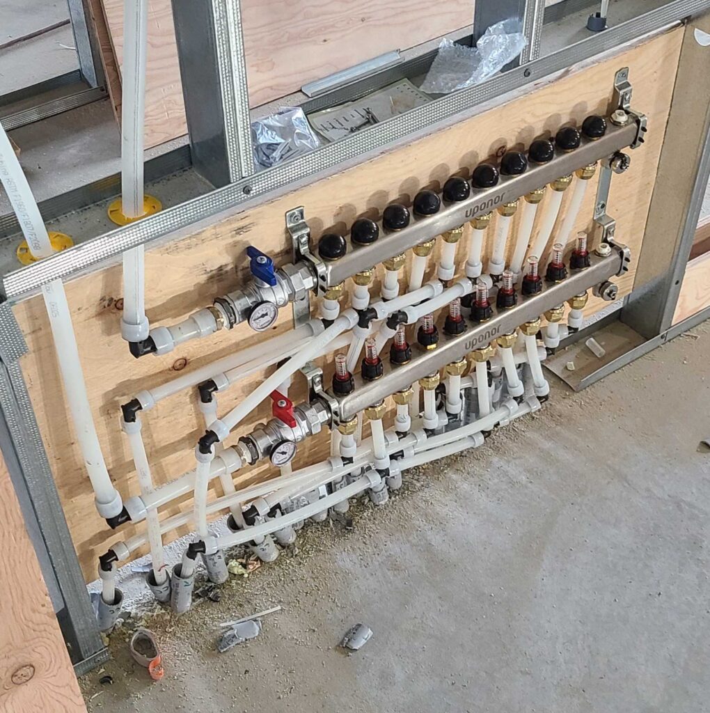
Manifold installation during construction.
The water being circulated is heated by means of an air-to-water heat pump that can heat the solution to about 28°C – adequate for most of the year. The heat pump receives support from a combined hot water booster / expansion tank that can elevate the temperature an additional 10°C or so depending upon heating demand. As an additional bonus, the heat pump also preheats water flowing into the domestic hot water tank. This is very economical as the heat pump can warm the cold well water far more efficiently – leaving the tank to heat warm water to about 48°C (as opposed to heating icy cold water to the same degree).
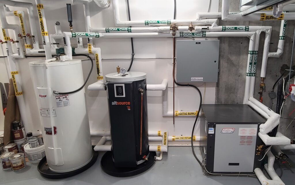
Mechanical Room from left to right: 60-gallon Hot Water Tank, combined Booster/Expansion Tank, interior Heat Pump unit (compressor). The wall mounted gray box houses direct digital controls for the heat pump system.
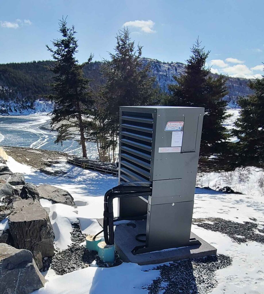
Exterior Heat Pump unit (fan/condenser)
It took roughly three days to warm up the house in late December when the in-floor radiation was initiated. So the thermal lag is considerable. It also takes three or four days for the house to cool appreciably if the system is shut down.
The floors don’t heat up to the same extent as electric systems employed in under-tile bathroom installations (which consume considerable energy) but they are always comfortable to the bare foot. For the entire winter we set the thermostats to 22°C and essentially left them untouched until the outside temperature in the summer reached that point. The consistency of comfort (temperature and humidity) throughout the heating season is amazing – seemingly oblivious to whatever is going on outside.
Now if I haven’t confused you too much, let’s move on to the second essential system – the Energy Recovery Ventilation (ERV) where I promise to confuse you completely!
First of all, this is not your run-of-the-mill heat exchanger chugging away 365 days a year providing fresh air to your home’s interior – the type of installation that you would find in a 1980’s R-2000 construct. It’s nothing glamorous to look at either: large, stainless-steel box. But inside that box is a sophisticated little computer that monitors the temperature and humidity of incoming air, the temperature and humidity of exhaust air, carbon dioxide (CO2) levels and volatile organic compounds (VOCs). It does so by sampling the air quality in the house every 10 minutes. The sample is assessed and the ERV decides what action to take – and gloriously, if there is no action required, it simply shuts itself down thus saving operational energy. In fact, I love entering the Mechanical / Utility Room to be met by silence.
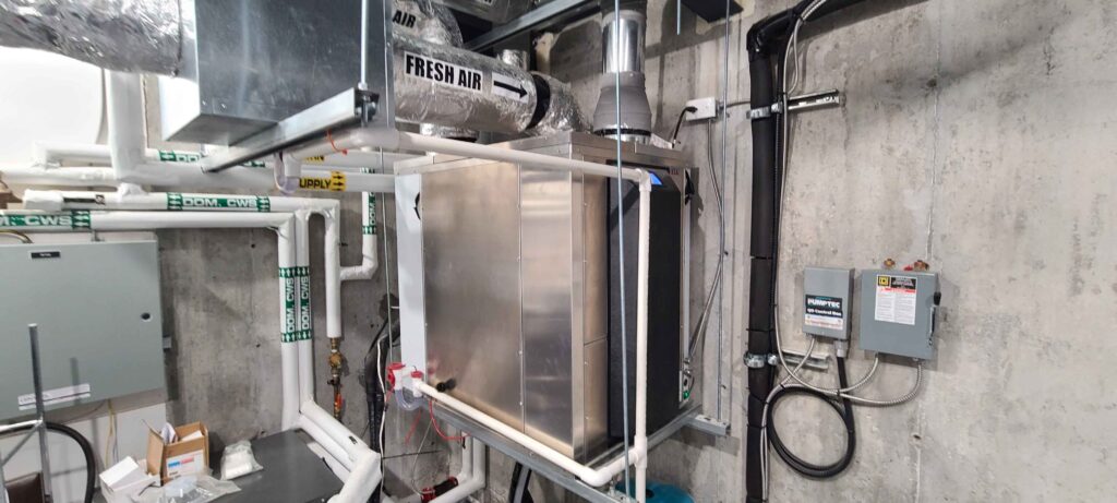
This ERV does not have an exchanger core like your old Venmar. It exchanges energy between incoming fresh air and outgoing stale air by means of a high efficiency heat pump. This has the added benefit of dehumidification during the summer months. Today (muggy July) the exterior humidity is 99%, but the interior humidity is 66%.
In operating mode, the unit’s ECM fan runs at about 40% capacity, but a wireless toggle switch in each bathroom and in the kitchen roughly doubles the fan speed to quickly remove steam and odour. The “ECM” stands for electronically commuted motor as opposed to a standard AC motor. This type of motor is about 30% more efficient, easier to control and never requires maintenance.
An abundance of carbon dioxide in an interior space can cause you to become tired and listless to the point of dizziness. It can also induce headaches, eye irritation and dry throat. VOCs are often identified as that “new car smell” but in your home, VOCs are emitted in aerosol sprays, cleaners and disinfectants, air fresheners, hobby supplies, and a wide range of building materials and furniture. The ERV’s threshold for CO2 and VOC is set at 1500 parts per million. Whenever these unwanted gasses build to that threshold, the ERV goes into overdrive to reduce the levels quickly.
Here’s a photo that I took today of the wireless remote touchscreen controller that is happily located on my kitchen countertop next to the coffee maker.
It just measured the CO2 and VOC as 796 and 406 PPM respectively – essentially healthy levels. And remarkably, please note that the humidity outside is 99% while the humidity inside is down to 66%. The first icon indicates the interior temperature to be 23.8°C. The outside temperature today is 22°C, but the incoming air temperature is 15.5°C. How can this be? Please allow me to explain what’s happening.
This sophisticated ERV offers an add-on component called a Geoboost. Here’s what it looks like:
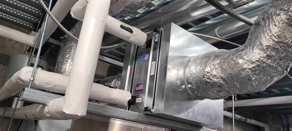
Simply put, it is a sheet metal box with a high efficiency exchange coil through which all the incoming supply air passes. Remarkably, there are no electronics whatsoever. The coil temperature is maintained at by means of a water/glycol solution that is pumped through 300 feet of 25 mm ABS pipe by a small circulation pump. The pump is wired to the ERV’s on-board computer and cuts in based on demand. The pipe is buried outside to an average depth of 10 feet, or at a point where the average temperature (based on what I have been able to gather) is between 6 and 8°C. This is sufficient (today) to pre-cool the supply air from outside down by 6.5°C. There was no special excavation for the ground loop. It was simply placed at the base of the foundation wall and in the service trench to the street.
Below is the exterior ground loop pipe (black) entry prior to backfilling the foundation and a photo of the interior condition as it passes through the foundation wall (plan view). The little red thingie is a 1 GPM pump.
So … does this equate to air-conditioning? Certainly not. But it’s practically free. I haven’t had sufficient summertime (as yet) to put this fully to the test. Don’t forget that the exposed concrete floors throughout the house represent a considerable thermal mass that will not quickly heat up or cool down.
But I am hopeful based on the cooling of incoming fresh air. Not that we get a lot or sweltering heat in Newfoundland. There are still icebergs outside my window.
Awesome setup Jim … glad to see it all working so well !
I’m most interested in the ventilation that is monitoring humidity, CO2, and VOCs.
Have you tested for radon or plan to do so? If so, I’m certainly willing to help.
I would be interested in makes and models of the mechanical equipment. Great experiment – been enjoying your experience tremendously. Hope you publish a summary of what you learnt, suggestions for similar projects.